Home
› 5 Pin Wire Diagram : Relay 5 Pin Wiring Diagram - Wiring Diagram And Schematic Diagram Images - 3 pin xlr connectors are standard amongst line level and mic level audio applications.
5 Pin Wire Diagram : Relay 5 Pin Wiring Diagram - Wiring Diagram And Schematic Diagram Images - 3 pin xlr connectors are standard amongst line level and mic level audio applications.
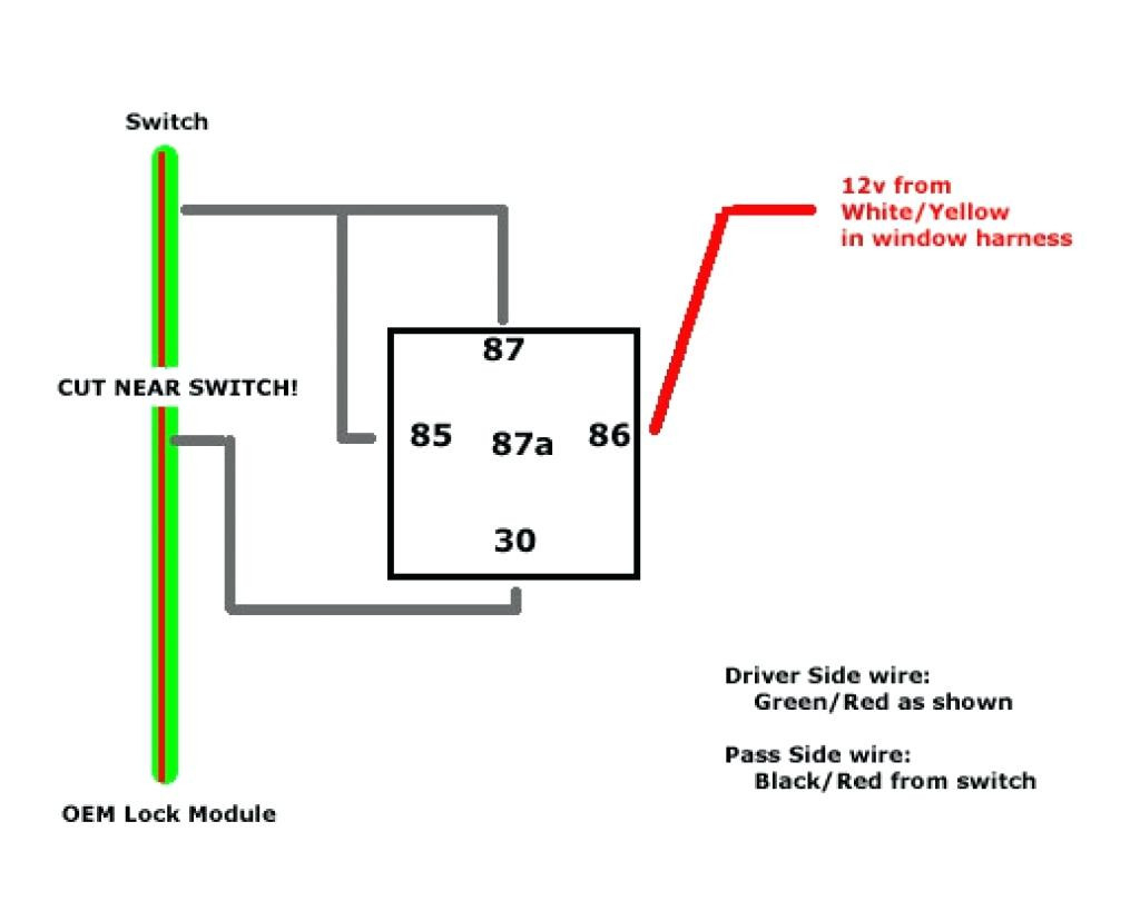
5 Pin Wire Diagram : Relay 5 Pin Wiring Diagram - Wiring Diagram And Schematic Diagram Images - 3 pin xlr connectors are standard amongst line level and mic level audio applications.. Find this pin and more on 12 v by robert romero. Xlr wiring diagrams and standards, for 3 & 5 pin xlr connectors. Here is a wiring diagram and pin out: 4 pin relay 4 pin relays use 2 pins (85 & 86) to control the coil and 2 pins (30 & 87) which switch power on a single circuit. The above diagram shows you the pin numbering for both male and female xlr.
Here is a wiring diagram and pin out: Details on polarity, colour coding and wiring standards. Additionally, wiring diagram provides you with time body by which the tasks are to be completed. Normally open or normally closed. We created this page to help people understand that not all microphones are wired the same way.
Rib Relay In A Box Wiring Diagram Sample from wholefoodsonabudget.com 2000 chevy impala owners manual. I did some preliminary digging to find a compatible wiring diagram for the switch but cannot find the voltage/amperage settings for the switch's integrated led. Learn how to wire a 4 or 5 pin relay with our wiring diagrams and understand how relays work. The usb cable has typically four wires to connect the a type connector. Trim all the wires to the same length, about 1/2 to 3/4 left exposed from the sheath. Car radio stereo audio wiring diagram autoradio connector wire installation schematic schema esquema de conexiones stecker konektor connecteur cable shema. I'm not concerned about the colours of the wires. 4 pin relay 4 pin relays use 2 pins (85 & 86) to control the coil and 2 pins (30 & 87) which switch power on a single circuit.
Details on polarity, colour coding and wiring standards.
Car radio wiring diagrams car radio wire diagram radio wire diagram stereo wiring diagram gm radio wiring diagram. Connect back right pin on relay (with the 3 pins facing you, pin in back on right) to the positive lead going to the motor drivers (in circuit diagram). Cut and strip (ground) black wire pin 24 and (+12v) yellow wire pin 11. Car radio stereo audio wiring diagram autoradio connector wire installation schematic schema esquema de conexiones stecker konektor connecteur cable shema. That means that you are controlling the positive side of the circuit with a switch, rather than the negative side. In this tutorial we will convert a 4pin ps4 to use a 5pin psu, there may other methods to do that but i found this is the easiest: Narva 7 and 12 pin trailer connectors comply with all relevant adrs. It shows the components of the circuit as simplified shapes, and the facility and signal connections amid the devices. Download vjd2 u66b user guide. Find this pin and more on 12 v by robert romero. Trim all the wires to the same length, about 1/2 to 3/4 left exposed from the sheath. Main 5 pin wire harness. If not, cut off connector and repeat above steps with new rj45 connector.
Details on polarity, colour coding and wiring standards. Normally open or normally closed. There are 2 types of 4 pin relay available; I did some preliminary digging to find a compatible wiring diagram for the switch but cannot find the voltage/amperage settings for the switch's integrated led. Here is a wiring diagram and pin out:
5 Pin Led Flasher Relay Wiring Diagram - Wiring Diagram from lh3.googleusercontent.com 2000 chevy impala owners manual. Here is a wiring diagram and pin out: Has anyone got a diagram for the wiring connections. Usb wiring diagram comes in handy when usb port or connector either of them malfunctions or completely out of order, also for engineers and step4: For example, just because two different microphones are 4 pin does not mean that they are wired the radio mic wiring diagram. The wiring diagram to the right shows how the contacts and lamps are wired internally. In this tutorial we will convert a 4pin ps4 to use a 5pin psu, there may other methods to do that but i found this is the easiest: Not all trailers have reverse lights, so consider.
Xlr wiring diagrams and standards, for 3 & 5 pin xlr connectors.
Here is a wiring diagram and pin out: 5 pin rocker switch wiring diagram. Pinout diagrams and wire colours for cat 5e, cat 6 and cat 7. You will need one 4 pins power cable and one 5 pins power cable and follow the images and diagram 4 pin trailer wiring diagram. Now connect connector pin and wires from the bunch acquire according to the color code and pinout of that particular usb connector on the page. Download vjd2 u66b user guide. I'm not concerned about the colours of the wires. On the other hand, this diagram is a simplified version of the structure. The above diagram shows you the pin numbering for both male and female xlr. Find this pin and more on 12 v by robert romero. Cut and strip (ground) black wire pin 24 and (+12v) yellow wire pin 11. Learn how to wire a 4 or 5 pin relay with our wiring diagrams and understand how relays work.
This type of connector is normally found on utvs, atvs and trailers that do not have their own braking system. Similar switches from the manufacturer with integrated leds i have seen have the led rated at (led voltage: Connect back right pin on relay (with the 3 pins facing you, pin in back on right) to the positive lead going to the motor drivers (in circuit diagram). Quality assurance momentary carling lighted 5 terminals 5 pin rocker switch wiring diagram. Rj45 wiring pinout for crossover and straight through lan ethernet network cables.
Relay Wiring Diagram 5 Pin | Wiring Diagram from annawiringdiagram.com Rj45 wiring pinout for crossover and straight through lan ethernet network cables. Cut and strip (ground) black wire pin 24 and (+12v) yellow wire pin 11. If not, cut off connector and repeat above steps with new rj45 connector. I'm not concerned about the colours of the wires. The chart and image above are correct for these models Car radio wiring diagrams car radio wire diagram radio wire diagram stereo wiring diagram gm radio wiring diagram. The above diagram shows you the pin numbering for both male and female xlr. An ethernet cable rj45 connector has 8 pins.
Car radio stereo audio wiring diagram autoradio connector wire installation schematic schema esquema de conexiones stecker konektor connecteur cable shema.
You'll be able to know exactly if the assignments should be accomplished, which makes it easier for. In this specific diagram, it is wired as a positive trigger relay. January 10, 2019january 10, 2019. I want to make up a lead with a 5 pin din at one end to fit an old 1980s tape deck, with a headphone plug on the other end to plug into the external speakers on a computer. For example, just because two different microphones are 4 pin does not mean that they are wired the radio mic wiring diagram. Main 5 pin wire harness. That means that you are controlling the positive side of the circuit with a switch, rather than the negative side. Not all trailers have reverse lights, so consider. I did some preliminary digging to find a compatible wiring diagram for the switch but cannot find the voltage/amperage settings for the switch's integrated led. Attach these wires to a compatible connector to power the arduino board (in. Rj45 wiring pinout for crossover and straight through lan ethernet network cables. Details on polarity, colour coding and wiring standards. Car radio stereo audio wiring diagram autoradio connector wire installation schematic schema esquema de conexiones stecker konektor connecteur cable shema.