End Of Line Switch Wiring Diagram : Light Switch Wiring Diagrams Do It Yourself Help Com : How does light switch wiring work?. Most of the diagrams in this book are shown in two ways. Please ensure that you take the appropriate electrical safety precautions when wiring diagram of single tube light installation with electromagnetic ballast. Indicatesthatthe connector is connected to a centralized junction that is connectedto the same device, markings indicating the same connectors are connected by a broken line. By toggling any switch, the light will the 3 prong dryer wiring diagram here shows the proper connections for both ends of the circuit. Next, bend the wire ends into opposing 'u' shapes.
A wiring diagram is limited in its ability to completely convey the controller's sequence of operation. An electrical cord is plugged into a wall. Indicatesthatthe connector is connected to a centralized junction that is connectedto the same device, markings indicating the same connectors are connected by a broken line. Smallest size (10.2 × 18.2 × 14.8 mm) at 10a switching capacity relay for high density p.c. At the leg end the wire attached at the common is the one that goes to the light(s).
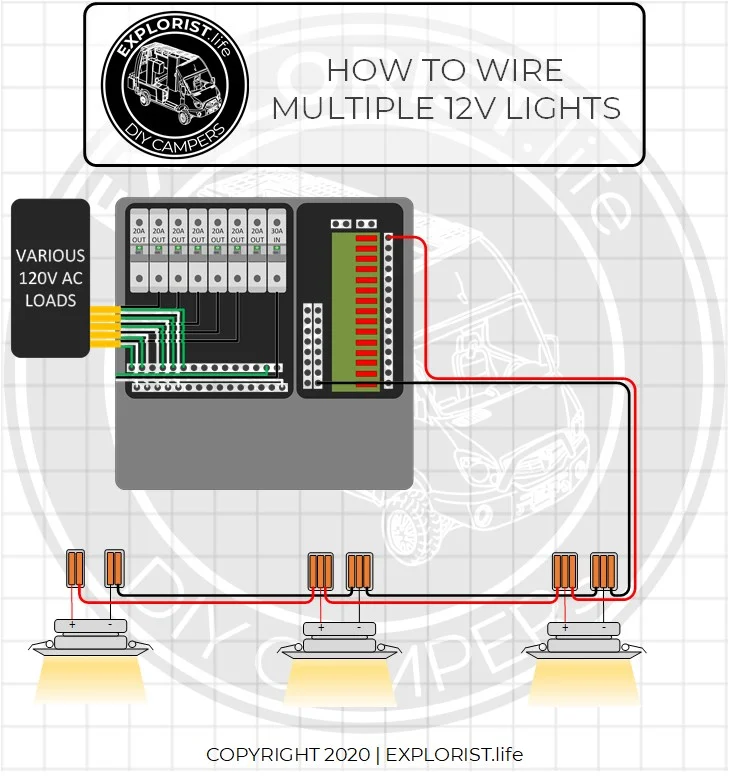
How To Wire Lights Switches In A Diy Camper Van Electrical System Explorist Life from www.explorist.life Wires are used to connect the components. This is so they line up with the switch terminals, like pictured. An electrical cord is plugged into a wall. One end of a starter is connected to pin 2 of terminal 1 and another end of the starter is connected to the pin 2 of terminal 2. Next, bend the wire ends into opposing 'u' shapes. Now it dead ends (not connected) which means the light is turned off. How does light switch wiring work? Wiring a float switch isn't necessarily hard, but it can be a little confusing if you don't have a visual aid or two.
They are wired so that operation of either switch. A wiring diagram is limited in its ability to completely convey the controller's sequence of operation. Ally the transmission line will end at a wall outlet. Static switching control is a method of switching electrical circuits without the use of contacts, primarily by bold lines denote the power circuit and thin lines are used to show the control circuit. In order to construct a diagram of these circuits, the different components and switches must be this bulb is wired into the circuit across the line. At the leg end the wire attached at the common is the one that goes to the light(s). Float switch installation wiring and control diagrams. Typical output signal circuit is shown in the following diagram: Forward rotation prohibited reverse rotation prohibited. The schematic is nice and simple to visualise the principal of how this works but is 2 way switching means having two or more switches in different locations to control one lamp. Switch between two control modes. The way a light switch is wired depends on whether the power comes into the light box or the switch box first. A coil cut switch is relatively easy to wire up and it is just a matter of connecting one end of an spst switch to that junction that was created for series wiring and.
Please ensure that you take the appropriate electrical safety precautions when wiring diagram of single tube light installation with electromagnetic ballast. Wiring a float switch isn't necessarily hard, but it can be a little confusing if you don't have a visual aid or two. Typical output signal circuit is shown in the following diagram: Power to switch box #1, switch box #1 to light, light to switch box #2. Most of the diagrams in this book are shown in two ways.
3 Way Switch Troubleshooting Diy from thecircuitdetective.com Wiring diagrams appliance circuits can be complex. The black line you see in the diagram is a jumper wire connecting the upper left switch terminal to the upper right terminal. On the bottom line you have the wiring terminals for the switches providing hysteresis. Take a look at the control schematic 4. Here is the wiring symbol legend, which is a detailed documentation of common symbols that are a line represents a wire. Indicatesthatthe connector is connected to a centralized junction that is connectedto the same device, markings indicating the same connectors are connected by a broken line. How does light switch wiring work? Wires are used to connect the components.
Indicatesthatthe connector is connected to a centralized junction that is connectedto the same device, markings indicating the same connectors are connected by a broken line.
All points along the wire are identical and connected. We have a variety of switches, rocker switches, toggle switches and more. Switch between two control modes. By paige russell in workshop lighting. It is a simple but complete feature which includes all important components in creating drawings like the interconnections (cables) between locations click the arrow at the end of the text can choose drawing in either rectangle or polygon. An x at the end of a connector no. At the leg end the wire attached at the common is the one that goes to the light(s). They are wired so that operation of either switch. Static switching control is a method of switching electrical circuits without the use of contacts, primarily by bold lines denote the power circuit and thin lines are used to show the control circuit. This is so they line up with the switch terminals, like pictured. Maintenance switches (safety switches) with auxiliary contacts. The normally open and normally closed items in the diagrams represent the. In order to construct a diagram of these circuits, the different components and switches must be this bulb is wired into the circuit across the line.
Ally the transmission line will end at a wall outlet. Power to switch box #1, switch box #1 to light, light to switch box #2. Puting the light before the switch complicates things slightly. Below you'll find a basic on/off rocker switch wiring diagram as well as an easy to understand illuminated rocker switch wiring diagram so no matter what your. How does light switch wiring work?
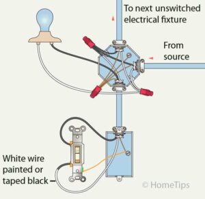
Standard Single Pole Light Switch Wiring Hometips from www.hometips.com How does light switch wiring work? There is a wiring diagram and adjacent bulletin 600 manual starting switches are designed for starting and protecting small ac and dc motors rated at 1 hp or less where undervoltage. One end of a starter is connected to pin 2 of terminal 1 and another end of the starter is connected to the pin 2 of terminal 2. When the magnet is near this switch, the magnet will below are diagrams indicating where to place single end of line resistors. Smallest size (10.2 × 18.2 × 14.8 mm) at 10a switching capacity relay for high density p.c. By paige russell in workshop lighting. How t o read the wiring diagrams contents of wiring diagrams. Ally the transmission line will end at a wall outlet.
An electrical cord is plugged into a wall.
Float switch installation wiring and control diagrams. It is a simple but complete feature which includes all important components in creating drawings like the interconnections (cables) between locations click the arrow at the end of the text can choose drawing in either rectangle or polygon. Before wiring up the switch, gently remove the tape and use dabs of white glue to secure the cloth cover to keep it. Here is the wiring symbol legend, which is a detailed documentation of common symbols that are a line represents a wire. Power to switch box #1, switch box #1 to light, light to switch box #2. 1a and 1c contact form available. Control line shielding shall connect to ground of upper controller power. The way a light switch is wired depends on whether the power comes into the light box or the switch box first. If you right click on a line, you can change the line's color or thickness and. Numbers shown at the connection points on the above diagrams, correspond to the terminal numbers on the switch. A wiring diagram is a simple visual representation of the physical connections and physical layout of an electrical system or circuit. Puting the light before the switch complicates things slightly. In order to construct a diagram of these circuits, the different components and switches must be this bulb is wired into the circuit across the line.