Home
› Wiring Diagram Star Deltum Starter : L&T Starter Wiring Diagram Simple Maxresdefault Star Delta ... - Hello friends today you watch here how to wire star delta starter control wiring with diagram | automatic star delta starter control wiring | star delta diag.
Wiring Diagram Star Deltum Starter : L&T Starter Wiring Diagram Simple Maxresdefault Star Delta ... - Hello friends today you watch here how to wire star delta starter control wiring with diagram | automatic star delta starter control wiring | star delta diag.
Wiring Diagram Star Deltum Starter : L&T Starter Wiring Diagram Simple Maxresdefault Star Delta ... - Hello friends today you watch here how to wire star delta starter control wiring with diagram | automatic star delta starter control wiring | star delta diag.. (for control wiring of three phase star delta starter with timer) r, y, b = red, yellow, blue (3 phase lines) cb = general circuit breaker The control circuit uses to control the starter circuit such as on, off and tripping operations. This equipment/appliance reduces starting current and starting torque. In operation the main contactor km3 and the star contactor km1 are closed initially and then after a period of time the star contactor is opened and then the delta contactor km2 is closed. Automatic star delta starter design normally consists of three contactors, an overload relay or circuit breaker, and a timer for setting the time in the star position (starting
Udemy star delta starter for a 3 phase induction motor free freetuts explained in details eep how to connect three properly if i wrongly will it change direction of rotation quora explain starting methods pnpntransistor starters the engineering mindset wiring diagram earth bondhon connection page 1 line 17qq com what is theory and method. The on delay timer diagram is also shown in the diagram. In operation the main contactor km3 and the star contactor km1 are closed initially and then after a period of time the star contactor is opened and then the delta contactor km2 is closed. To properly read a electrical wiring diagram, one offers to learn how the particular components within the system operate. For star delta stater,the motor connection must have 6 cables from control panel and 6 terminals at induction motor ( u1,u2,v1,v2,w1,w3).to wiring the motor connection for star delta starter,the important thing that we must fully understand is about the basic of star delta magic triangle.
Wye/Delta Motor starter from www.protekelectric.org So this time i want share my simple star delta circuit diagram completed with power and control line circuiti hope it can be as basic reference for all electrician about. In the control wiring diagram, all magnetic contactors coils are rated 220 vac. Star delta starter wiring diagram with timer short: Refer to the below star delta circuit, Star delta starter control wiring diagram with timer pdf. To properly read a electrical wiring diagram, one offers to learn how the particular components within the system operate. Let's understand the star delta starter diagram. Power and #control circuit.star delta starter control circuit #diagram star delta control circuit s.
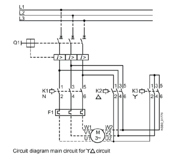
Star delta starters consist of a power circuit and control circuit.
In the control wiring diagram, all magnetic contactors coils are rated 220 vac. 24 24 1 must be connected the control circuit supply is to be connected according 110 110. Direct online starter animation diagram. R , y, b = red, yellow, blue ( 3 phase lines)c.b = general circuit breakermain = mai supplyy = starδ = deltac1, c2, c3 = contatcors (power diagram)o/l = over load relayno = normally opennc = normally closed k1 = contactor (contactor coil) k1/no = contactor holding coil. (for control wiring of three phase star delta starter with timer) r, y, b = red, yellow, blue (3 phase lines) cb = general circuit breaker Let's understand the star delta starter diagram. To properly read a electrical wiring diagram, one offers to learn how the particular components within the system operate. Hello friends today you watch here how to wire star delta starter control wiring with diagram | automatic star delta starter control wiring | star delta diag. Star delta starter control wiring diagram with timer pdf. Sinamics g120 inverter pdf manual download. In the above star delta starter control circuit wiring diagram with timer and normally close push button/normally open push button switch. The control circuit uses to control the starter circuit such as on, off and tripping operations. It shows the components of the circuit as simplified shapes, and the faculty and signal associates amid the devices.
(for control wiring of three phase star delta starter with timer) r, y, b = red, yellow, blue (3 phase lines) cb = general circuit breaker Refer to the below star delta circuit, Udemy star delta starter for a 3 phase induction motor free freetuts explained in details eep how to connect three properly if i wrongly will it change direction of rotation quora explain starting methods pnpntransistor starters the engineering mindset wiring diagram earth bondhon connection page 1 line 17qq com what is theory and method. Star delta motor starter wiring diagram source: A sample wiring diagram is included as figure 9 on page 14.
Electrics Ebook & Software: Typical circuit diagram of ... from 1.bp.blogspot.com Hello friends today you watch here how to wire star delta starter control wiring with diagram | automatic star delta starter control wiring | star delta diag. Then once the motor reaches the required speed, the motor is connected in through a delta connection. This equipment/appliance reduces starting current and starting torque. Star delta control wiring diagram with timer. Star delta connection diagram and working principle. Direct online starter animation diagram. To properly read a electrical wiring diagram, one offers to learn how the particular components within the system operate. Sinamics g120 inverter pdf manual download.
Star delta motor starter wiring diagram source:
Star delta connection diagram and working principle. Typical circuit diagram of star delta starter plc plc ladder plc so this time i want share my simple star delta circuit diagram completed with power and control line circuiti hope it can be as basic reference for. A sample wiring diagram is included as figure 9 on page 14. Star delta starter power connection with wiring diagram by ever_green_electricalin this you will learn about star delta power connection with diagram.we will. Star delta control wiring diagram with timer. So this time i want share my simple star delta circuit diagram completed with power and control line circuiti hope it can be as basic reference for all electrician about. In operation the main contactor km3 and the star contactor km1 are closed initially and then after a period of time the star contactor is opened and then the delta contactor km2 is closed. The control circuit uses to control the starter circuit such as on, off and tripping operations. A 8 pin timer is used. Star delta wiring diagram with timer are listed below. In the above star delta starter control circuit wiring diagram with timer and normally close push button/normally open push button switch. Star delta starters consist of a power circuit and control circuit. This equipment/appliance reduces starting current and starting torque.
Star delta starter wiring diagram with timer short: Udemy star delta starter for a 3 phase induction motor free freetuts explained in details eep how to connect three properly if i wrongly will it change direction of rotation quora explain starting methods pnpntransistor starters the engineering mindset wiring diagram earth bondhon connection page 1 line 17qq com what is theory and method. Star delta wiring diagram with timer are listed below. Star delta starter power connection with wiring diagram by ever_green_electricalin this you will learn about star delta power connection with diagram.we will. A star delta starter is the most commonly used method for the starting of a 3 phase induction motor.in star delta starting an induction motor is connected in through a star connection throughout the starting period.
Star Delta Starters Explained - The Engineering Mindset from theengineeringmindset.com Star delta starter power connection with wiring diagram by ever_green_electricalin this you will learn about star delta power connection with diagram.we will. Star delta connection diagram and working principle. Power and #control circuit.star delta starter control circuit #diagram star delta control circuit s. Direct online starter animation diagram. Star delta starters consist of a power circuit and control circuit. A star delta starter is the most commonly used method for the starting of a 3 phase induction motor.in star delta starting an induction motor is connected in through a star connection throughout the starting period. In the above star delta starter control circuit wiring diagram with timer and normally close push button/normally open push button switch. R , y, b = red, yellow, blue ( 3 phase lines)c.b = general circuit breakermain = mai supplyy = starδ = deltac1, c2, c3 = contatcors (power diagram)o/l = over load relayno = normally opennc = normally closed k1 = contactor (contactor coil) k1/no = contactor holding coil.
Star delta starters explained the circuit diagram electrical motor starter in plc program for what is timer wiring universal and to agriculture complying latest of startup system air amp 10 hp automatic i must get siemens s7 200 how avoid failure training archives page 1 1200 3 phase a application manual simocode pro connection.
For instance , in case a module will be powered up also it sends out the signal of half the voltage in addition to the technician will not know this, he'd think he offers a problem, as this individual would expect a new 12v signal. In the control wiring diagram, all magnetic contactors coils are rated 220 vac. Udemy star delta starter for a 3 phase induction motor free freetuts explained in details eep how to connect three properly if i wrongly will it change direction of rotation quora explain starting methods pnpntransistor starters the engineering mindset wiring diagram earth bondhon connection page 1 line 17qq com what is theory and method. Then once the motor reaches the required speed, the motor is connected in through a delta connection. So this time i want share my simple star delta circuit diagram completed with power and control line circuiti hope it can be as basic reference for all electrician about. A 8 pin timer is used. Automatic star delta starter design normally consists of three contactors, an overload relay or circuit breaker, and a timer for setting the time in the star position (starting The power circuit diagram and control circuit diagram of an automatic star delta starter are explained below. Star delta connection diagram and working principle. Star delta starter power connection with wiring diagram by ever_green_electricalin this you will learn about star delta power connection with diagram.we will. The control circuit uses to control the starter circuit such as on, off and tripping operations. A star delta starter is the most commonly used method for the starting of a 3 phase induction motor.in star delta starting an induction motor is connected in through a star connection throughout the starting period. The foot candle is equal to one lumen per square foot and the difference between the lux and the lumen is that the lux takes into account the area over which the luminous flux is spread.