Home
› Wiring Diagrams For Electric Trailer Brakes : Electric Trailer Brake Wiring Diagram / This wiring electric trailer brakes diagram model is more acceptable for sophisticated trailers and rvs.
Wiring Diagrams For Electric Trailer Brakes : Electric Trailer Brake Wiring Diagram / This wiring electric trailer brakes diagram model is more acceptable for sophisticated trailers and rvs.
Wiring Diagrams For Electric Trailer Brakes : Electric Trailer Brake Wiring Diagram / This wiring electric trailer brakes diagram model is more acceptable for sophisticated trailers and rvs.. The blue (brake output) wire must be connected to the trailer connector's brake wire. I go over all the basics on wiring up your vehicle trailer harness and electric brakes. Connected the plug to car and all working ok. They also provide a wire for a ground connection. Ensure it is sealed off and cannot create a short circuit with any other wire or the chassis.
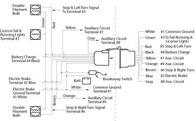
The service brake circuit must be disconnected from an existing trailer plug. It reveals the parts of the circuit as streamlined forms, as well as the power and signal connections in between the gadgets. I go over all the basics on wiring up your vehicle trailer harness and electric brakes. Elecbrakes must be connected to trailer wiring circuits as outlined in the wiring diagram. The black wire is the power supply line to the brake control.
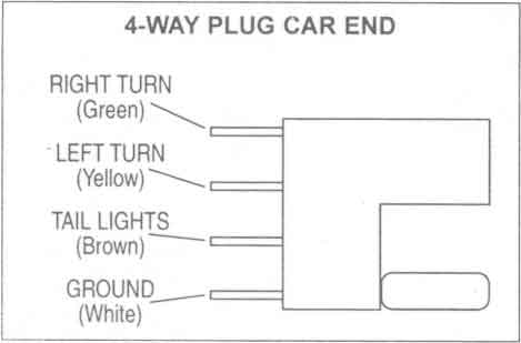
Trailer Wiring Diagrams Johnson Trailer Co from johnsontrailerco.com Following the wiring diagram included with the controller, run the blue wire through the firewall and to the rear of the vehicle where it will connect to the trailer connector. Blue = electric brakes or hydraulic reverse disable (see blue wire notes below.) The four wires control the turn signals, brake lights and taillights or running lights. The blue (brake output) wire must be connected to the trailer connector's brake wire. Variety of trailer breakaway wiring schematic. The black wire is the power supply line to the brake control. Each component ought to be set and connected with different parts in particular manner. White pin for the ground.
Elecbrakes must be connected to trailer wiring circuits as outlined in the wiring diagram.
Do not disturb the position of the switch. Electric trailer brake wiring and parts diagrams click here to shop for electric trailer brakes and brake parts the two main types of electric brake assemblies for axles 7k and below are forward self adjusting (fsa) and manual adjusting. A wiring diagram is a streamlined conventional pictorial representation of an electric circuit. Once again, thanks to you for. Dexter axle wiring diagram how to wire the electric over trailer brake airstream forums testing magnets for control activator protective connector humphreys hydraulic disc actuator k71 651 00 brakes rh installing on your nev r adjust 12 25 x 3 375 faulty love neo trailers. Assortment of electric trailer brake wiring schematic. Connected the plug to car and all working ok. Each component ought to be set and connected with different parts in particular manner. A wiring diagram is a streamlined traditional pictorial representation of an electrical circuit. The 5th pin, a blue wire, gives power to operate (or disable) the trailer brakes. The red (stoplight) wire must be connected to the cold side of the brake pedal stoplight switch. With this kind of an illustrative manual, you are going to be capable of troubleshoot, stop, and total your assignments with ease. As the name implies, they use four wires to carry out the vital lighting functions.
Dexter axle wiring diagram how to wire the electric over trailer brake airstream forums testing magnets for control activator protective connector humphreys hydraulic disc actuator k71 651 00 brakes rh installing on your nev r adjust 12 25 x 3 375 faulty love neo trailers. When you use your finger or stick to the circuit along with your eyes, it may be easy to mistrace the circuit. It reveals the parts of the circuit as streamlined forms, as well as the power and signal connections in between the gadgets. The blue (brake output) wire must be connected to the trailer connector's brake wire. Trailer wiring diagrams trailer wiring connectors various connectors are available from four to seven pins that allow for the transfer of power for the lighting as well as auxiliary functions such as an electric trailer brake controller, backup lights, or a 12v power supply for a winch or interior trailer lights.
Electric Trailer Brake Wiring Diagram from www.easternmarine.com The black wire is the power supply line to the brake control. The service brake circuit must be disconnected from an existing trailer plug. Variety of trailer breakaway wiring schematic. 2 axle trailer brake wiring page 1 line 17qq com diagram lights brakes routing wires connectors tandem for two fusebox and component theft paoloemartina it a design sources visualdraw funny tech tip other random car stuff the 24 hours of lemons forums instructions to wire electric etrailer camper diagrams full version hd quality diagramclothing bandbannamaria 2 axle trailer… read more » Splice down line from the switch; It reveals the parts of the circuit as streamlined forms, as well as the power and signal connections in between the gadgets. Ensure it is sealed off and cannot create a short circuit with any other wire or the chassis. The red (stoplight) wire must be connected to the cold side of the brake pedal stoplight switch.
Connected the plug to car and all working ok.
The black wire is the power supply line to the brake control. Primus brake controller wiring diagram (nov 16, ) ― Assortment of electric trailer brake wiring schematic. It reveals the parts of the circuit as streamlined forms, as well as the power and signal connections in between the gadgets. Do not disturb the position of the switch. Collection of wiring diagram for utility trailer with electric brakes. This short video is about trailer brakes, electric brakes and wiring. 2 axle trailer brake wiring page 1 line 17qq com diagram lights brakes routing wires connectors tandem for two fusebox and component theft paoloemartina it a design sources visualdraw funny tech tip other random car stuff the 24 hours of lemons forums instructions to wire electric etrailer camper diagrams full version hd quality diagramclothing bandbannamaria 2 axle trailer… read more » The service brake circuit must be disconnected from an existing trailer plug. Blue = electric brakes or hydraulic reverse disable (see blue wire notes below.) The 5th pin, a blue wire, gives power to operate (or disable) the trailer brakes. The red (stoplight) wire must be connected to the cold side of the brake pedal stoplight switch. The red (stoplight) wire must be connected to the cold side of the brake pedal stoplight switch.
This short video is about trailer brakes, electric brakes and wiring. With this kind of an illustrative manual, you are going to be capable of troubleshoot, stop, and total your assignments with ease. Electric trailer brake wiring and parts diagrams click here to shop for electric trailer brakes and brake parts the two main types of electric brake assemblies for axles 7k and below are forward self adjusting (fsa) and manual adjusting. A wiring diagram is a streamlined conventional pictorial representation of an electric circuit. The red (stoplight) wire must be connected to the cold side of the brake pedal stoplight switch.
Billavista Com Trailer Brake Controller Tech Article By Billavista from www.billavista.com The black wire is the power supply line to the brake control. 7 way plug wiring diagram standard wiring* post purpose wire color tm park light green (+) battery feed black rt right turn/brake light brown lt left turn/brake light red s trailer electric brakes blue gd ground white a accessory yellow this is the most common (standard) wiring scheme for rv plugs and the one used by major auto manufacturers today. 2 axle trailer brake wiring page 1 line 17qq com diagram lights brakes routing wires connectors tandem for two fusebox and component theft paoloemartina it a design sources visualdraw funny tech tip other random car stuff the 24 hours of lemons forums instructions to wire electric etrailer camper diagrams full version hd quality diagramclothing bandbannamaria 2 axle trailer… read more » The red (stoplight) wire must be connected to the cold side of the brake pedal stoplight switch. The blue (brake output) wire must be connected to the trailer connector's brake wire. Dexter axle wiring diagram how to wire the electric over trailer brake airstream forums testing magnets for control activator protective connector humphreys hydraulic disc actuator k71 651 00 brakes rh installing on your nev r adjust 12 25 x 3 375 faulty love neo trailers. Assortment of electric trailer brake wiring schematic. It reveals the elements of the circuit as streamlined forms, and also the power and signal connections between the gadgets.
With this kind of an illustrative manual, you are going to be capable of troubleshoot, stop, and total your assignments with ease.
Once again, thanks to you for. Ensure it is sealed off and cannot create a short circuit with any other wire or the chassis. Trailer wiring diagrams trailer wiring connectors various connectors are available from four to seven pins that allow for the transfer of power for the lighting as well as auxiliary functions such as an electric trailer brake controller, backup lights, or a 12v power supply for a winch or interior trailer lights. This short video is about trailer brakes, electric brakes and wiring. The red (stoplight) wire must be connected to the cold side of the brake pedal stoplight switch. It shows the components of the circuit as streamlined shapes, and the power and also signal connections in between the devices. I go over all the basics on wiring up your vehicle trailer harness and electric brakes. White pin for the ground. Splice down line from the switch; The service brake circuit must be disconnected from an existing trailer plug. You almost certainly know already that primus brake controller wiring diagram is among the top issues online. 7 way plug wiring diagram standard wiring* post purpose wire color tm park light green (+) battery feed black rt right turn/brake light brown lt left turn/brake light red s trailer electric brakes blue gd ground white a accessory yellow this is the most common (standard) wiring scheme for rv plugs and the one used by major auto manufacturers today. 7 pin trailer brake wiring diagram source: