Home
› Magnetek Motor Wiring Diagram : Magnetek Century Ac Motor Wiring Diagram | Free Wiring Diagram : Interconnecting wire routes may be shown approximately, where particular.
Magnetek Motor Wiring Diagram : Magnetek Century Ac Motor Wiring Diagram | Free Wiring Diagram : Interconnecting wire routes may be shown approximately, where particular.
Magnetek Motor Wiring Diagram : Magnetek Century Ac Motor Wiring Diagram | Free Wiring Diagram : Interconnecting wire routes may be shown approximately, where particular.. Molded case circuit breaker and thermal overload relay. A diagram of the ladder program contained inside the plc memory specifically for this function is also included the forward contactor is wired in the normal direct phasing of the motor terminal, whereas the the control circuit which commands the switching selection of these two magnetic contactors is. The above wiring diagram assumes your magnetic starter has a 240v coil. It works by using a single phase power. Shows the wiring diagram for a full voltage mag netic reversing starter.
Magnetic motor starters, as seen in figure 6. The above wiring diagram assumes your magnetic starter has a 240v coil. Check the drive control diagram to see if the series field should be connected into the armature circuit. Mc motor starter wiring diagram with cb, mc, o/l, no, nc. It works by using a single phase power.
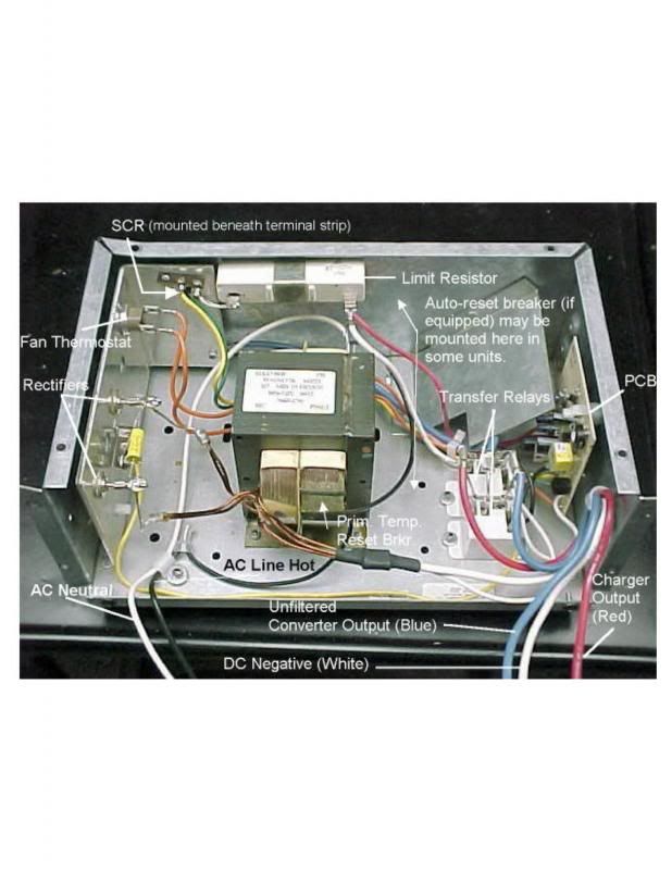
Magnetek Century Ac Motor Wiring Diagram from schematron.org Assuming the electric eld to be zero (this is the case of a dc motor), with reference to the quantity of charge dq found. Connection diagrams, or wiring diagrams, show the components of the control circuit in a semblance of their actual physical locations. Now, consider a wire where a uniform current i is owing. Single phase motor wiring diagrams. Home » wiring diagrams » magnetic contactor wiring diagram. On the other hand, this diagram is a simplified version of the arrangement. Wiring diagrams show the connections to the controller, while line diagrams show circuits of the operation of the controller. Magnetic motor starter working principle.
Wiring diagrams show how the wires are connected and where they should located in the actual device unlike a pictorial diagram, a wiring diagram uses abstract or simplified shapes and lines to show components.
A magnetic starter or other motor controllers may include overload devices, or they may be an integral part of the motor, particularly with small motors. Single phase motor wiring diagrams. Electric motor that has a great horse power would require a large initial torque in order to fight the inertia and load diagram below will give you a new experience for those who want to learn how to rewinding induction motors in accordance with the following specifications. Combining a manual motor starter and a magnetic contactor. Magnetic motor starter working principle. In the diagram above, the motor at point 'a' rotates the shaft and. 4 wire reversible psc motor. They can be used as a guide when wiring the controller. Use wiring diagrams to assist in building or manufacturing the circuit or computer. Connection diagrams, or wiring diagrams, show the components of the control circuit in a semblance of their actual physical locations. How to wire a garage diagram sample. Wiring diagram motor control system refrence perfect square d motor control center wiring diagrams. The stator consists is a device or core containing start and run windings (of copper wire) wound around a central core to create a magnetic field.
Molded case circuit breaker and thermal overload relay. June 6, 2019june 6, 2019. The closer to the wire coils, the greater the power generated in those coils. 24.01.2020 · the wiring diagram is a little unclear in the box and i dont want to burn the magnetic starter is furnas the motor is a baldor t 5 hp 3wiring instructions for magnetic starters important if the compressor has a factory. Check the drive control diagram to see if the series field should be connected into the armature circuit.
Magnetek Universal Electric Motor Wiring Diagram Series 28af from schematron.org Check the drive control diagram to see if the series field should be connected into the armature circuit. 24.01.2020 · the wiring diagram is a little unclear in the box and i dont want to burn the magnetic starter is furnas the motor is a baldor t 5 hp 3wiring instructions for magnetic starters important if the compressor has a factory. Wiring diagrams and control methods for three phase ac motor. Wiring diagrams show how the wires are connected and where they should located in the actual device unlike a pictorial diagram, a wiring diagram uses abstract or simplified shapes and lines to show components. A wiring diagram normally gives details concerning the family member setting as well as setup of tools and terminals on the tools, to aid in structure or servicing the device. Wiring diagram delco remy alternator archives jasonaparicio. Wiring diagrams show the connections to the controller, while line diagrams show circuits of the operation of the controller. Home » wiring diagrams » magnetic contactor wiring diagram.
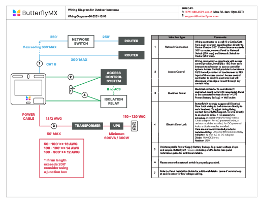
Wiring diagram for magnetic door lock best valid wiring diagram.
4 wire reversible psc motor. Wiring diagram delco remy alternator archives jasonaparicio. A magnetic eld is generated by a owing current: In the diagram above, the motor at point 'a' rotates the shaft and. Wiring diagrams show the connections to the controller, while line diagrams show circuits of the operation of the controller. Single phase motor wiring diagrams. Electric motor wiring diagrams & guides. The stator consists is a device or core containing start and run windings (of copper wire) wound around a central core to create a magnetic field. Use wiring diagrams to assist in building or manufacturing the circuit or computer. Connection diagrams, or wiring diagrams, show the components of the control circuit in a semblance of their actual physical locations. Check the drive control diagram to see if the series field should be connected into the armature circuit. The closer to the wire coils, the greater the power generated in those coils. The diagram shows a simple motor using direct current (dc).
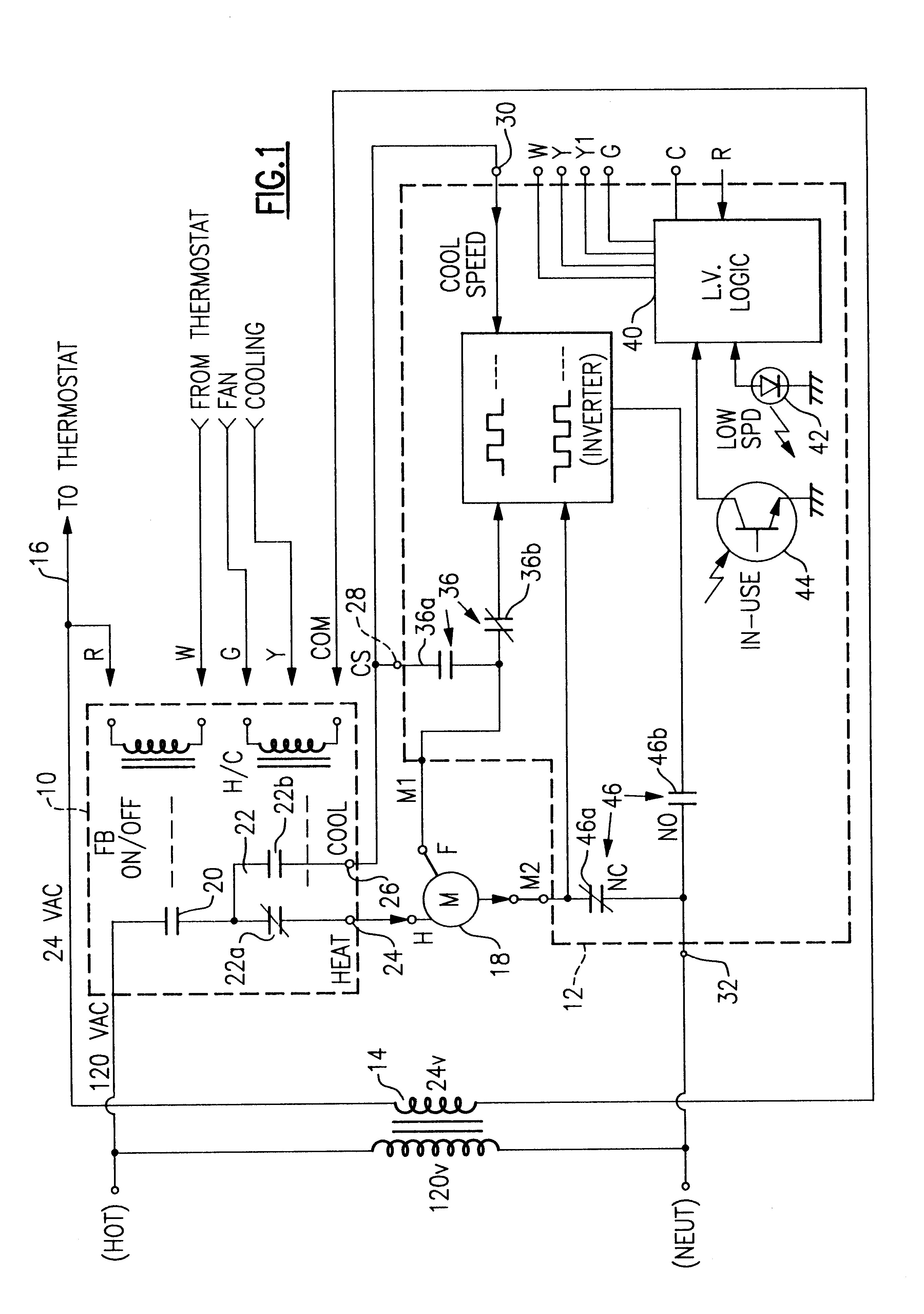
Magnetic motor starter working principle. Wiring diagrams show how the wires are connected and where they should located in the actual device unlike a pictorial diagram, a wiring diagram uses abstract or simplified shapes and lines to show components. Fleming's left hand rule can be used to explain why the coil. Interconnecting wire routes may be shown approximately, where particular. In this motor wiring diagram we can see the key components and the wiring of an universal motor
Gould Century Motor Wiring Diagram | Wiring Diagram from 2020cadillac.com June 6, 2019june 6, 2019. A single phase motor is an electrically powered rotary machine that can turn electric energy into mechanical energy. In this motor wiring diagram we can see the key components and the wiring of an universal motor This effect can be used to make an electric motor. Use wiring diagrams to assist in building or manufacturing the circuit or computer. He universal motor is a type of electric motor that can operate on either ac or dc power and uses an electromagnet as its stator to create its magnetic field. A coil of wire carrying a current in a magnetic field experiences a force that tends to make it rotate. Wiring diagrams show the connections to the controller, while line diagrams show circuits of the operation of the controller.
A wiring diagram normally gives details concerning the family member setting as well as setup of tools and terminals on the tools, to aid in structure or servicing the device.
Ac80, ac90, ac100 single phase motors. Interconnecting wire routes may be shown approximately, where particular. Use wiring diagrams to assist in building or manufacturing the circuit or computer. On the other hand, this diagram is a simplified version of the arrangement. 3 phase motor starter wiring diagram pdf wiring diagram technic. Wiring diagram for magnetic door lock best valid wiring diagram. Wiring diagrams and control methods for three phase ac motor. A magnetic starter or other motor controllers may include overload devices, or they may be an integral part of the motor, particularly with small motors. The above wiring diagram assumes your magnetic starter has a 240v coil. Wiring diagram for alternator to battery save starter motor solenoid. Assuming the electric eld to be zero (this is the case of a dc motor), with reference to the quantity of charge dq found. Electric motor wiring diagrams & guides. The diagram offers visual representation of a electrical structure.