Home
› Decoder Logic Diagram And Truth Table / DECODER LOGIC DIAGRAM AND TRUTH TABLE - Auto Electrical Wiring Diagram / Truth tables offer a simple and easy to understand tool that can be used to determine the output of any logic gate or circuit for all input combinations.
Decoder Logic Diagram And Truth Table / DECODER LOGIC DIAGRAM AND TRUTH TABLE - Auto Electrical Wiring Diagram / Truth tables offer a simple and easy to understand tool that can be used to determine the output of any logic gate or circuit for all input combinations.
Decoder Logic Diagram And Truth Table / DECODER LOGIC DIAGRAM AND TRUTH TABLE - Auto Electrical Wiring Diagram / Truth tables offer a simple and easy to understand tool that can be used to determine the output of any logic gate or circuit for all input combinations.. Q.1 which of the following circuits come under the class of combinational logic circuits? One of these outputs will be active high based on the one of these four outputs will be '1' for each combination of inputs when enable, e is '1'. The list of all possible inputs are arranged. You can even realise logic functions using decoders and some additional gates. You can enter logical operators in several different formats.
Featuring a purple munster and a duck, and optionally showing intermediate results, it is one of the better instances of its kind. From the decoder truth table we can write the boolean expression for each output line, just follow where the output gets high and form an and logic based on the values of i1 and i0. Read about decoder (combinational logic functions ) in our free electronics textbook. Truth table of 2:4 decoder. Logic diagrams and truth tables.
Encoder Logic Diagram With Truth Table - Wiring Diagram & Schemas from i.imgur.com Logical expression for sum 4. Truth table in the logical diagram of figure 3, each mini term is implemented by an and gate with two input terminals. We will discuss each herein and demonstrate ways to convert between them. And and gate can be used as the basic decoding element, because its output is high only when from the truth table we can draw the circuit diagram as shown in figure below. 3 to 8 decoder designing 5. A logic gate is a device that can perform one or all of the boolean logic operations and when combined, several gates can make a complex logical evaluation system that has many inputs and outputs. Use the buttons below (or your keyboard) to enter a proposition, then gently touch the. It is the reverse process of an encoder.
Now input the table given.
Representing data as binary values means we have to. Logic diagram of 2:4 decoder. If we see the logic diagram of decoder inside all possible minterms of sop are realized. One of these outputs will be active high based on the one of these four outputs will be '1' for each combination of inputs when enable, e is '1'. Use the buttons below (or your keyboard) to enter a proposition, then gently touch the. Dcode also makes it possible to find the boolean logic function/expression from a truth table. Binary uses base 2, so we have just two possible values 1 or 0. So, it's very easy to realize any boolean expression by taking it's required output as minterm and oring with extra or gate. Featuring a purple munster and a duck, and optionally showing intermediate results, it is one of the better instances of its kind. A decoder is a combinational logic circuit that is used to change the code into a set of signals. The decoder is internally formed by logic gates and its internal connections figure 2. A truth table is a mathematical table used in logic—specifically in connection with boolean algebra, boolean functions, and propositional calculus—which sets out the functional values of logical. 3 to 8 decoder working, truth table and circuit diagram.
Let's write the truth table for the encoder using the information that the encoder gives outputs that are physical addresses of the inputs. Finding address is just one of uncountable applications of decoders. A truth table is a mathematical table used in logic—specifically in connection with boolean algebra, boolean functions, and propositional calculus—which sets out the functional values of logical. Thanks to your feedback and relevant comments, dcode has developed the best 'truth table' tool, so feel free to write! However, my circuit could hold up to 15 instructions.
Binary Decoders: Basics, Working, Truth Tables & Circuit Diagrams from circuitdigest.com Logic diagrams and truth tables. It is called a decoder because it does the reverse of encoding, but we will begin our study of encoders and decoders with decoders because they are simpler. Computers are based on electrical circuits where we can detect whether current is flowing or not. So, it's very easy to realize any boolean expression by taking it's required output as minterm and oring with extra or gate. This tool generates truth tables for propositional logic formulas. The list of all possible inputs are arranged. Decoders are important logic blocks that find a wide variety of applications in the design of digital systems. Let's write the truth table for the encoder using the information that the encoder gives outputs that are physical addresses of the inputs.
Thanks to your feedback and relevant comments, dcode has developed the best 'truth table' tool, so feel free to write!
However, my circuit could hold up to 15 instructions. Read about decoder (combinational logic functions ) in our free electronics textbook. The logical diagram of the 3×8 line decoder is given below. It is the reverse process of an encoder. Use the buttons below (or your keyboard) to enter a proposition, then gently touch the. The truth table of 2 to 4 decoder is shown below. A decoder takes input lines and has output lines. From the decoder truth table we can write the boolean expression for each output line, just follow where the output gets high and form an and logic based on the values of i1 and i0. Hope you might have got some fundamental concepts about this topic by observing the digital logic circuits and truth tables and their applications. Here we only need value 0 though 9 rest now input d, c, b, a as in which case d is msb and a is lsb. Finding address is just one of uncountable applications of decoders. A decoder is a circuit that changes a code into a set of signals. One of the characteristics that we must take into account is that a logic circuit does not have to be represented.
Dcode also makes it possible to find the boolean logic function/expression from a truth table. In this video, i have explained 3 to 8 decoder by following outlines:1. The logic diagram consists of gates and symbols that can directly replace an expression in boolean arithmetic. Here we only need value 0 though 9 rest now input d, c, b, a as in which case d is msb and a is lsb. The block diagram and truth table of full subtractor are as below.
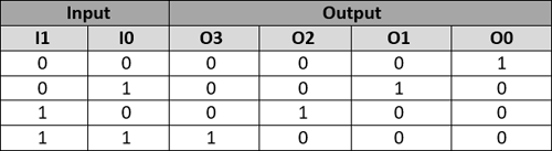
truth table and logic diagram for decoder 4 to 16 lineHCC4514B/HCC4515B - Electronic Circuit ... from 4.bp.blogspot.com The truth table of 2 to 4 decoder is shown below. Truth tables offer a simple and easy to understand tool that can be used to determine the output of any logic gate or circuit for all input combinations. Gates such as and gate. At any one time, only one input line has a value of 1. Let's write the truth table for the encoder using the information that the encoder gives outputs that are physical addresses of the inputs. Truth table of 2:4 decoder. It is the reverse process of an encoder. A decoder is a circuit that changes a code into a set of signals.
The notation may vary depending on what industry you're engaged in, but the basic concepts are the same.
Gates such as and gate. A decoder takes input lines and has output lines. They're a versatile, interdisciplinary tool. It is the reverse process of an encoder. 3 to 8 decoder truth table: You can enter logical operators in several different formats. Logical expression for sum 4. Read about decoder (combinational logic functions ) in our free electronics textbook. However, my circuit could hold up to 15 instructions. Computers are based on electrical circuits where we can detect whether current is flowing or not. Let's write the truth table for the encoder using the information that the encoder gives outputs that are physical addresses of the inputs. Binary uses base 2, so we have just two possible values 1 or 0. One of the characteristics that we must take into account is that a logic circuit does not have to be represented.