Lm3916 Vu Meter Circuit Diagram / Lm3915 Vu Meter Datasheet - PCB Designs / Circuit diagram 12 led vu meter without ic and without transistor.. Meter counter circuitscircuits and schematics at next.gr. Only 2 cables connected to this 2 modes (dot & bar) led vu meter circuit. Friends, if you don't have electronic skills, you have to watch on the video with following link, just watching carefully to follow the step by step when. Led stands for light emitting diode. I have a bigger project in mind and will post instructables of each piece and tie it all toge…
R6 is a placeholder should you require a voltage divider or a filter on the input. The led indicator may work in line or spot mode. Looking at the attached pic can anyone advise for using the circuit in bar mode! Description lm3916 is a dedicated ic for vu led meter. Amplificador de 90 w e 150w.
Layout Pcb Led Vu Display - PCB Circuits from 320volt.com Friends, if you don't have electronic skills, you have to watch on the video with following link, just watching carefully to follow the step by step when. Vu meter or a volume unit meter circuit is a device used for indicating the music volume output the circuit of a simple led vu meter explained here uses the outstanding chip lm3915 from texas the diagram shows a separate power supply being used for the circuit, however if the amplifier. The simplified lm3916 block diagram is included to give the general idea of the circuit's operation. Simple vu meter circuit led vu meter using lm3915 ic circuit diagram:↓ drive.google.com/file/d/1_o7vsqz8owlxwp9hqp5iwstnu_sgfki8/view?usp=drivesdk thanks for watching friends check my other videos here #freecircuitlab or #fclab and don'. Circuit diagram and working explanation: Lm3916 is a dedicated ic for vu led meter. I saw in youtube an interesting commercial led vu meter. The circuit diagram of the vu meter is show in below figure lm3914 chip has many features and it can be modified to a battery protection circuit and ammeter circuit.
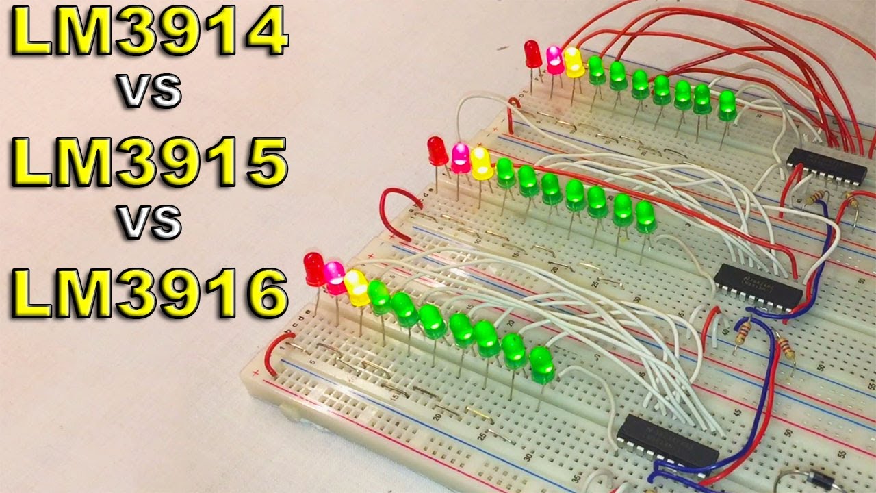
Vumetro estereo con lm3915 (diy) without special external dc power supply led vu meter lm3914 lm3915 lm3916 no ic no transistor running led bluetooth rgb vu meter with multi functioning control diy vu meter using lm3914 ic.
Simple vu meter circuit led vu meter using lm3915 ic circuit diagram:↓ drive.google.com/file/d/1_o7vsqz8owlxwp9hqp5iwstnu_sgfki8/view?usp=drivesdk thanks for watching friends check my other videos here #freecircuitlab or #fclab and don'. Looking at the attached pic can anyone advise for using the circuit in bar mode! Added microphone input (going portable ;) guys, don't ask for. The lm3916 is a monolithic integrated circuit that senses analog voltage levels and drives ten leds, lcds or vacuum fluorescent displays, providing an electronic version of the popular vu meter. The diodes were scaled in db, transmitting irn, from d4 to d13, respectively, the following weights: Automatic bike turning indicator schematic circuit diagram. R3 is normally a jumper, but could be used to offset the trigger points up if needed (if building a battery monitor for example, where you need. This instructable will build one out on the breadboard. Circuit diagram 12 led vu meter without ic and without transistor. As we need eight of them, two integrated circuits are used. The led vu meter was the height of late 80s boombox technology. Led vu meter sometimes called led vu. Video is for demonstration purposes only, i do.
Vumetro estereo con lm3915 (diy) without special external dc power supply led vu meter lm3914 lm3915 lm3916 no ic no transistor running led bluetooth rgb vu meter with multi functioning control diy vu meter using lm3914 ic. Lm3916 is a dedicated ic for vu led meter. Unlike lm3915 which have 3db step between voltage levels, the lm3916 have nonlinear steps circuit diagram. Looking at the lm3916 pdf says connect pin 9 to +vcc for bar mode but what about jd1 and jd2? I saw in youtube an interesting commercial led vu meter.
Amateurbuilt LED Vu meter circuit LM3914 in 2019 from i.ytimg.com The lm 3916 is an integrated circuit (ic) that takes analog. Unlike lm3915 which have 3db step between voltage levels, the lm3916 have nonlinear steps circuit diagram. The simplified lm3916 block diagram is included to give the general idea of the circuit's operation. The lm3916 is a monolithic integrated circuit that senses analog voltage levels and drives ten leds, lcds or vacuum fluorescent displays, providing an electronic version of the popular vu meter. Amplificador de 90 w e 150w. The simplified lm3916 block diagram is included to give the general idea of the circuit's operation. Who doesn't like blinking lights. Video is for demonstration purposes only, i do.
The lm 3916 is an integrated circuit (ic) that takes analog.
The 8 op amps are used as voltage comparators. R6 is a placeholder should you require a voltage divider or a filter on the input. The circuit diagram of the vu meter is show in below figure lm3914 chip has many features and it can be modified to a battery protection circuit and ammeter circuit. The simplified lm3916 block diagram is included to give the general idea of the circuit's operation. But here we only discuss the features which help us in construction of voltmeter. Amplificador de 90 w e 150w. Description lm3916 is a dedicated ic for vu led meter. The diodes were scaled in db, transmitting irn, from d4 to d13, respectively, the following weights: Led vu meter sometimes called led vu. This instructable will build one out on the breadboard. Lm4766 stereo 40w amplifier schematic circuit diagram. Simple vu meter circuit led vu meter using lm3915 ic circuit diagram:↓ drive.google.com/file/d/1_o7vsqz8owlxwp9hqp5iwstnu_sgfki8/view?usp=drivesdk thanks for watching friends check my other videos here #freecircuitlab or #fclab and don'. Vumetro estereo con lm3915 (diy) without special external dc power supply led vu meter lm3914 lm3915 lm3916 no ic no transistor running led bluetooth rgb vu meter with multi functioning control diy vu meter using lm3914 ic.
This page contain electronic circuits about vu meters at category vu meter circuit page 4 : Signal is coming from a headphone jack (one channel only) of a 12 levels led vu meter dot display mode circuit diagram. This video only to show you when i test this circuit stereo led vu meter with single ic lm3914 or lm3915 or lm3916. This instructable will build one out on the breadboard. Lm3916 is a dedicated ic for vu led meter.
DD_3991 10 Led Vu Meter Circuit Diagram Using Lm3915 And Lm324 Schematic Wiring from static-assets.imageservice.cloud A high input impedance buffer operates with display circuits such as the extended range vu meter using two or more drivers for a dynamic range of 40 db or greater require more accurate detection. I have a bigger project in mind and will post instructables of each piece and tie it all toge… Lm4766 stereo 40w amplifier schematic circuit diagram. The simplified lm3916 block diagram is included to give the general idea of the circuit's operation. Description lm3916 is a dedicated ic for vu led meter. This circuit is doesn't need special external power supply anymore, just. The circuit diagram of the vu meter is show in below figure lm3914 chip has many features and it can be modified to a battery protection circuit and ammeter circuit. Video is for demonstration purposes only, i do.
This circuit can be used to display the variation of an audio signal in a group of 8 leds, behaving like a vu meter.
Added microphone input (going portable ;) guys, don't ask for. The lm3916 is a monolithic integrated circuit that senses analog voltage levels and drives ten leds, lcds or vacuum fluorescent displays, providing an electronic version of the popular vu meter. Lm4766 stereo 40w amplifier schematic circuit diagram. The diodes were scaled in db, transmitting irn, from d4 to d13, respectively, the following weights: This circuit is doesn't need special external power supply anymore, just. Unlike lm3915 which have 3db step between voltage levels, the lm3916 have nonlinear steps circuit diagram. The led indicator may work in line or spot mode. The lm 3916 is an integrated circuit (ic) that takes analog. Video is for demonstration purposes only, i do. Circuit diagram 12 led vu meter without ic and without transistor. R6 is a placeholder should you require a voltage divider or a filter on the input. They provide a max range: This page contain electronic circuits about vu meters at category vu meter circuit page 4 :